
Powering Your Business
Powering Your Business
SGDB Series
Programmable AC/DC Power Distribution Units

SGDB Series
Power Distribution Units (PDU) are designed and manufactured for use in
industrial automation and automatic test systems. PDUs are completely software
controlled. Current and voltage measurements are made with high precision for
all output channels. Current limit can be determined for each channel. When the
specified limit current is reached, it can be preferred to turn-off the channel
automatically or keep it open and warn the user.
These Units are designed as
solid state in modular structure and in BPS configuration. Each 5/6 channel is
controlled by 1 microprocessor. Therefore, when a channel has reached the set
limit value, programmed reaction is performed in a short time around 10
microseconds.
The unit's main processor
continuously monitors all channels and communications with submodules during normal
operation. In this way, if a situation that cannot be controlled due to any
malfunction (component, etc.) occurs, the input voltage is isolated from the
output very quickly. This isolation is provided by high capacity circuit
breaker(s) placed at the input.
This isolation mechanism can
also be triggered both by the physical Emergency Stop Button and the
soft-button on the PDU Manager software. More than one PDU can be controlled
with a single Emergency Stop Button by making a chain connection with the
Emergency Stop Connector on the unit. In addition, each output channel is also
protected by a thermal fuse.
IP address and similar basic
settings can be made when necessary, via the Serial Interfaces on the front
panel of the unit. In addition, embedded software updates can also be made with
these interfaces, and low level detailed information is obtained about the
status of unit’s subcomponents when necessary. PDU tests itself during startup.
These test stages can also be monitored via those serial interfaces.
The front panel also includes a
time counter that shows how long the unit has been active. Besides, the LED indicators
for; input voltage, network connection, data communication and erroneous situations,
are also on the front panel. There are also output LED indicators which are directly
connected to each output channel.
With the PDU Manager software
supplied with the unit, the output channels of one or more PDUs can be included
in different turn-on/off scenarios. With the 4-level scenario structure, many
channels and sub-scenarios can be created/included within each other.
PDU Manager software keeps detailed measurement
records at 1/3 seconds intervals as well as the turn-on/off times of channels.
Thanks to this data collection capability, it is possible to retrospectively
examine how much the systems fed from the PDU, draw current at any given
moment. For more detailed information about the PDU Manager software, please
see the PDU Manager section.

Features
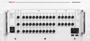
Input: 240-300 VDC
Output: 45 Channels
536 Amps Switching Capacity
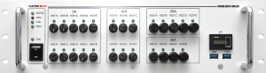
Input: 20-30 VDC
Output: 25 Channels
400 Amps Switching Capacity
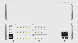
Input: 20-30 VDC
Output: 25 Channels
1200 Amps Switching Capacity
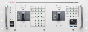
Input: 380VAC 50Hz
115VAC 400Hz
Output: 18 Channels
768 Amps Switching Capacity